LAG circuit is an important circuit that can be added to control systems in order to increase accuracy and make response faster.
What effect does the LAG circuit have on the system?
When added to the system, the LAG circuit provides a convenient way to move a certain pole to the right. Therefore; increasing the accuracy and making the response faster. I have talked in a previous summary about the effects of pole locations on the stability of the system. You can read that summary here.
Drawbacks of adding a LAG circuit to the system
Even though moving poles to the right increases the accuracy and makes the response faster, it makes the system less stable.
Where do we add the LAG circuit?
LAG circuit is always added in the low power section just before the system. This is because if the LAG circuit was added in the high power section, high power resistances and capacitors will be needed when designing the LAG circuit.
Diagram of LAG circuit
Deducing the Transfer Function (TF) of LAG circuit (4 steps)
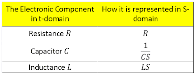
- Change the LAG circuit from t-domain to Laplace domain (S-domain) according to the following:
Therefore; the LAG circuit becomes: - Find the Input Resistance
Example
Design a suitable circuit to remove the old pole (S+4) in the following control system by replacing it with a new pole (S+2). Sketch the circuit indicating whether it is LEAD OR LAG, and derive its Transfer Function TF. Finally, find the values of R1, R2, and C?
It is clear from the designed circuit that a = 4 > b = 2. Therefore; the designed circuit is a LAG Circuit. Also notice how the pole (-4) was replaced by the pole (-2)
Finding the values of R1, R2, and C
Note: If the resulting values of R1 and C are illogic or don't exist on the market, we assume another value for R2 and repeat calculations. Therefore; it is highly recommended that you do all the calculations in an EXCEL spreadsheet.
*****This Summary is available as PDF File
Click here to get a PDF Copy*****

![[Summary] How "LAG Circuit" is Used in Control Systems [Summary] How "LAG Circuit" is Used in Control Systems](https://blogger.googleusercontent.com/img/b/R29vZ2xl/AVvXsEivdV-4EeLP4HbPkpEu8vF03P5JaETNrCxnyw9LjKQFXAEZlAlBWNeu7x9XDVu6mEgOmFmEkzXWUDspHS8Au8Xywxa0ZYjYvnlYKqZ-mqTit76Apw-7aibFUVHmix5gk-hEcbPfmWASWHrDjndHB_1t78AgFyY-l0H4ib0m0_mAD8z072ujiDX_Irgu/s1600-rw-e90/LAG%20Circuit.png)


%20-%20Automatic%20Control%20Systems.png)


