What is "Wheatstone Bridge"?
It is one of the bridges used in DC circuits. It is basically an electrical circuit that is used to accurately find the value of any unknown resistance.
Who invented Wheatstone Bridge and when?
The Wheatstone bridge was invented by Samuel Hunter Christie (sometimes spelled "Christy") in 1833 and improved and popularized by Sir Charles Wheatstone in 1843. One of the Wheatstone bridge's initial uses was for soils analysis and comparison.
The structure of Wheatstone Bridge Circuit
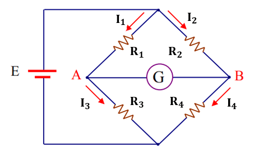
The Wheatstone bridge circuit consists of two parallel branches, each branch contains two resistors connected in series, and these two branches are fed by a constant voltage source, which causes an electric current to pass through them. Moreover; a device used to measure voltage (usually a galvanometer) is connected - as shown in the figure below - to balance the bridge.
How to use Wheatstone Bridge Circuit to find the value of an unknown resistance
First, we replace the resistance of the fourth arm of the Wheatstone bridge circuit with the unknown resistance. Next, we change the value of one of the resistances of the remaining arms (mostly the resistance of the second arm) until the Wheatstone bridge circuit is balanced. Finally, we apply the Balance condition of Wheatstone bridge circuit to find the value of the unknown resistance.
What do we mean by "Wheatstone Bridge Circuit's balance"?
The Wheatstone bridge circuit balance is achieved when the potential difference between points A and B is zero. Meaning that there is no potential difference across the galvanometer and therefore no current passes through it.
Balance condition of Wheatstone Bridge Circuit
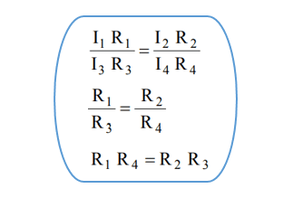
In order for Wheatstone bridge circuit to be balanced, the following equation must be true:
The derivation of the balance condition of Wheatstone Bridge Circuit
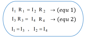
We already know that when Wheatstone bridge circuit is balanced, the potential difference between points A and B is zero. Concluding that the resistance voltage of the first arm = the resistance voltage of the second arm, and the resistance voltage of the third arm = the resistance voltage of the fourth arm. Moreover; and since the current through the galvanometer in the case of the balanced bridge is zero, then the current through the resistance of the first arm = the current through the resistance of the third arm, and the current through the resistance of the second arm = the current through the resistance of the fourth arm.
and by dividing equation 1 by equation 2, we get the following
The general solution of Wheatstone bridge circuit (the accurate solution)
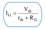
This solution is used to find the value of the current passing through the galvanometer, and to do that we use the Thevenin's theorem. We find the equivalent Thevenin's circuit and then the value of the current passing through the galvanometer is equal to the Thevenin's voltage divided by the sum of both the Thevenin's and galvanometer's resistances as follows
First, we calculate the Thevenin's voltage (Kirchhoff's Voltage Law & Voltage Divider Law are used here)
Second, we calculate Thevenin's resistance
The "Simplified Mathematical Approximation" to the general solution of Wheatstone bridge Circuit
This Simplified Mathematical Approximation is also used to find the value of the current passing through the galvanometer. However; it can only be used when the values of the resistances of the first, second, and third arms of Wheatstone bridge circuit are equal and the value of the resistance of the fourth arm differs a little from them (a difference of no more than 5%). Only if that is true, we can deduce an approximate but accurate mathematical expression from the general solution of Wheatstone bridge circuit to calculate the passing current through the galvanometer as follows:
First, we calculate Thevenin's voltage
Since the difference in the resistance of the fourth arm is small compared to the value of 2R, then we can neglect it, so we have:
Second, we calculate Thevenin's resistance
Since the difference in the resistance of the fourth arm is small compared to the value of R, then we can neglect it in both the numerator and denominator


